Aruba Switches and Trancievers

Vendors tend to lock down the type of transceivers you can use on their SFP/SFP+ and QSFP ports. They do this for a number of reasons but mainly in the spirit of support and quality (which I can understand). there are a number of guidelines around agreed upon by networking vendors that fall under Multi-Source Agreement (MSA). MSA specifications will dictate many physical characteristics, but not necessarily the electrical designs. For that reason, a transceiver may work in one switch/module, but not in another due to design differences not taken into consideration. Vendors will say that many low-cost products do not properly code the MSA required fields for type, distance, media type among other fields, or they may incorrectly identify the part, causing the switch to enable them with settings not appropriate for the type of transceiver inserted.

TL;DR it’s basically, use unsupported transceivers at your own risk and if it’s found to cause an issue, it won’t be supported.

I’ve got some 10gig going now in my home lab environment between my Aruba lab gear and Ubiquiti UDM-PRO, whilst it was pretty much plug and play on the Ubiquiti side (I am using their transceivers), on the Aruba I had to go and fiddle in the console to get it working. If you’re not managing via Aruba Central, it is a straight forward command.

Aruba-2930F# allow-unsupported-transceiver
Warning: The use of unsupported transceivers, DACs, and AOCs is at your own risk and may void support and warranty. Please see HPE Warranty terms and conditions.

Do you agree and do you want to continue (y/n)?

Hit Y to confirm
If you’re using Aruba Central, you’ll just also need to enable support mode.

Aruba-2930F# aruba-central support-mode enable
Aruba-2930F# allow-unsupported-transceiver
Aruba-2930F# write memory
Aruba-2930F# aruba-central support-mode disable

Once done, reboot your switch and the Transceiver will come online and begin to operate (unless it’s too cheap and faulty…), you can verify it’s there by issuing the following command

# show tech transceivers

Cmd Info : show tech transceivers

transceivers

Transceiver Technical Information:
 Port # | Type      | Prod #     | Serial #         | Part #
 -------+-----------+------------+------------------+----------
 10    *| SFP+SR    |       ??   | unsupported      |

In my case, I can see the transceiver but no information.

Power BI Gateway SSL Issues with managed AWS RDS SQL Server instances

I had a customer call up and explain their Power BI reports had stopped working, they’re not managed so after working a few things out we got to work and jumped into their Datawarehouse environment in AWS. After a quick look we could see that their RDS SQL Server instance had TLS turned on and that no one had managed or bothered to rotate the certificate which had now expired. This is a very quick and painless process (since it’s a managed instance) and simply requires a reboot. Once loaded, refreshing a report would result in an error of Something went wrong, and looking in the details we could see The certificate chain was issued by an authority that is not trusted.

You also need to ensure to load the AWS RDS Root certificates onto their Power BI Gateway and Reporting server, downloading them from AWS here and then loading them into the trusted certificate authority in the Windows Certificate store. Once done, we could see reports refreshing and pulling data as expected.

Moral of the story? Just because it’s managed doesn’t mean it’s set and forget…

Time Hierarchy in Active Directory

Time is more critical in Active Directory than many admins realise. Time inaccuracy can cause logs to mismatch or things like license failures for anything with DRM. Larger time differences can begin to cause authentication failures since Keberos relies on accurate time or affect replication health.

By default, all AD member machines synchronise with any available domain controller, and in turn domain controllers will synchronise with the PDC Emulator of that domain. This article by Microsoft explains most of the above along with a similar overview of setting up Time Sync correctly. Whenever doing a large audit for an on-premise AD customer or have the chance to build out a new AD Forest, we always recommend ensuring that the PDC gets it’s time from an accurate external time source, and I’ll usually go as far as setting up a set and forget GPO to manage this to ensure newer PDCs get this treatment.

To ensure we target only our PDC emulator we can create a WMI filter that we can use against the Group Policy object that we’ll be creating shortly. The following WMI query will filter a PDC Emulator in an AD environment

select * from Win32_ComputerSystem where DomainRole = 5

Next step is to create the Group Policy Object, in this case I’ve create a PDC External Time Sync GPO, open it up and go to Computer Configuration > Policies > Administrative Templates > System > Windows Time Service > Time Providers. We now want to configure the following settings as follows

Set Configure Windows NTP Client to Enabled
For NtpServer enter your NTP servers details: ntp.nml.csiro.au,0x9 ntp.monash.edu,0xa
For Type set to NTP
Set Enable Windows NTP Client to Enabled
Set Enable Windows NTP Server to Enabled

It’s also important to ensure you’re specifying the correct flags to ensure reliable time, with my example I’ve specified a primary and secondary time source to minimise any potential drift when Windows decides to synchronise. By making the primary NTP server flag 0x9, we made it “Client 0x08 + SpecialInterval 0x01” and as for the second NTP time server.
By making the secondary NTP peer flag 0xa, we made it “0x08 Client + 0x02 UseAsFallbackOnly”.The following options are available to use with w32tm.

0x01 SpecialInterval
0x02 UseAsFallbackOnly 
0x04 SymmatricActive 
0x08 Client

The final GPO should look something like this with the WMI filter attached an linked to an OU with your DCs.

Since I’m based in Australia I’ll tend to use au.pool.ntp.org or use the Australian Governments NMI NTP service, which requires you to get your public IP whitelisted but is unlikely to be poisoned or attacked unlike the NTP Pool project.

Hope that helps.

Bypass Windows 11 TPM Setup Checks

Quick one – I’m doing some testing in my home lab environment with Windows 11 and this box doesn’t have a TPM (so it’s not enabled in Hyper-V). Booting up the Windows 11 iso and trying to install will tell you that it’s unsupported. To get around that, load the setup as normal and once you reach the language and time screen press Shift+F10 to bring up the command prompt.  Type regedit and hit enter to launch Reg Edit for the pre-install environment.  Navigate to the HKEY_LOCAL_MACHINE\SYSTEM\Setup registry hive and create a new Key called LabConfig.  Now under LabConfig create two DWROD (32-bit) values, one BypassTPMCheck and the other BypassSecureBootCheck and set both of these to a value of 1.  If you don’t have enough RAM allocated you can also add a DWORD of BypassRAMCheck and value of 1.

Once you’re done close up Regedit and the Command Prompt and you can start the setup process and install as normal.

AWS and Windows Activation

Quick one today where I was on a client server hosted in AWS that wasn’t activated and trying to activate it via Settings App throws and error. Like most large scale cloud vendors (except Azure), AWS use KMS to activate their windows machines, however sometimes the servers need some help to reach the internal KMS servers at Amazon – especially so when using your own DNS servers.

Open an administrative PowerShell console and enter the following commands

Import-Module "C:\\ProgramData\\Amazon\\EC2-Windows\\Launch\\Module\\Ec2Launch.psd1"
Add-Routes
Set-ActivationSettings

Then perform an activate online command as per a normal KMS activation (or you can wait…)

slmgr /ato

And that should get it activated and the watermark removed.

RDP to Windows Login Screen

I was recently resurrecting an old demo environment in AWS which consisted of a few EC2 virtual machines, however upon trying to login, I quickly realised that the account password had expired and by default Windows Remote Desktop doesn’t have an ability to change passwords since you’re not presented with the logon screen.  We didn’t have console access nor was there any other remote access like ConnectWise Control and  since the only credential we had expired, we had to think outside the box.

Luckily RDP can fall back to authentication via the logon screen and ask for login details after you connect. To achieve this, we firstly need to disable Network Level User Authentication or NLA on the remote machine, by tweaking the following registry key (this can also be done remotely).

Set-ItemProperty -Path 'HKLM:\System\CurrentControlSet\Control\Terminal Server\WinStations\RDP-Tcp' -Name "UserAuthentication" -Value 0

Once you’ve applied that setting one way or another (using something like Amazon SSM or Azure Virtual Machine Run Command) we then need to create an RDP file, open up Remote Desktop connection, enter the IP and hit Save As to create a file.  Open it up in Notepad or your favorite text editor and add the following line to the end of the file

enablecredsspsupport:i:0

This disables the Credential Security Service Provider or CredSSP support and forces your connection to authenticate via the logon screen.

This setting is also handy for RDP farms or hosts that require interactive logins.  Just remember that NLA needs to be turned off for this to work.

See Supported RDP properties with Remote Desktop Services on Microsoft Learn (RIP MSDN) for more info and supported parameters.

Australian FTTP via Telstra not connecting to FortiGate

We recently had a customer take advantage of a free upgrade from FTTN (Fibre to the Node) to FTTP (Fibre to the Premise) for their NBN (National Broadband Network) service. However during cut-over the FortiGate wasn’t picking up connectivity on the WAN port, this had the on-site guy stumped for 10 minutes until we jumped on and took a look. In HFC days, you’d sometimes have to “spoof” the MAC address to get it working – but in this case it was something else… Ethernet auto-negotiate.

We hard-coded the WAN port to 100 full duplex and it kicked in like a charm. The following command lets you edit an interface and set the speed accordingly.

edit WAN1
set speed 100full
end

While it’s not something I’ve experienced with Enterprise Ethernet installations, this also rings true in certain cases of fibre installs we would sometimes see customer NTDs or NTU (such as Cisco or MRV) also not connect for similar reasons, so liasing with the ISP we’d ensure both sides of the cable are set to the same setting.

Sync multiple Pi-Hole Configs

For my home network, I run Pi-Hole in docker containers in separate hosts. Whenever making a change such as creating a local DNS entry on one Pi-hole means logging into the other Pi-hole and making the same change, not ideal. So I’ve tried looking for a solution to this. I did give Gravity sync a go however seemed a little hard to get going. Doing my Google search I also stumbled on Orbital-Sycn on GitHub which seems to do the same thing albeit much easier to configure and get going.

Using Orbital sync, it behaves similar to a HA pair where one becomes the primary and the config is synchronised to the secondary nodes. It was super simple to get going, making sure that it was on the correct docker network so it can see all the Pi-Hole containers in my network I then just creating the additional container using the docker compose file below.

version: '3'
services:
  orbital-sync:
    image: mattwebbio/orbital-sync:1
    environment:
      PRIMARY_HOST_BASE_URL: 'https://pihole1.home.lab'
      PRIMARY_HOST_PASSWORD: 'supersecretpassword'
      SECONDARY_HOSTS_1_BASE_URL: 'https://pihole2.home.lab'
      SECONDARY_HOSTS_1_PASSWORD: 'supersecretpassword'
      INTERVAL_MINUTES: 5

Replace the environment variables with settings for your setup. Based on this compose file, orbital-sync connects my two Pi-Hole containers and synchronises them every 5 minutes.

Additional configuration variables can be found on the CONFIG page on the orbital-sync GitHub.

Fix FortiGate HA out of sync

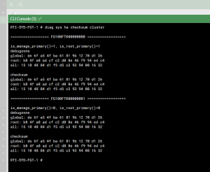
Sometimes after performing a Firmware upgrade on FortiGate HA pairs, I find that after sometime the cluster still stays out of sync and won’t synchronise. I usually find this is because the checksums of the config files on each or some members are different. To quickly check if this is the case, fire up the CLI and run the following command that will output the HA checksum.
# diag sys ha checksum cluster
If the output don’t match and we’re happy with the configuration of the primary we can issue a checksum recalculate by issuing the following command
# diag sys ha checksym recalculate
Just entering the command without options recalculates all checksums. You can specify a VDOM name to just recalculate the checksums for that VDOM.

SAML SSO for FortiWeb Admin interface

I was recently engaged with a large health-care provider in deploying a set of FortiWeb VMs to protect a number of web applications. Part of this deployment included setting up Single-Sign on for the admin interface using Microsoft Entra ID (Azure AD). While the process is fairly straightforward it is a little confusing at some points, so I’ve wrote this just in case you or I need this again.
Start off by creating an Enterprise Application in Microsoft Entra, browse the gallery and use the pre-built FortiWeb Web Application Firewall (which is used client based web authentication) – instead we’ll use it to configure the admin login. Enable Single sign-on and enter the Basic SAML configuration details as follows:

Identifier (Entity ID): http://10.0.0.1/metadata
Reply URL (Assertion Consumer Service URL): https://10.0.0.1:4443/saml/?acs
Sign on URL: https://10.0.0.1:4443/saml/login

The important part here is that the identifier runs on http and without the admin port, where as your reply and sign on URLs will need to go via https to the admin port.  Copy the Login URL (the logout URL is almost always the same…) and Microsoft Entra Identifier as we’ll need these shortly.  Add yourself or test user we’ll be logging in with.  We can now move onto configuring the FortiWeb.

Login and navigate to Security Fabric > Fabric Connectors and click on the FortiGate and select edit.  Once in, we’ll enable Single Sign-On mode toggle and enter some details as follows:

SP Address: IP of FortiWeb (primary if HA)
Default Login Page: Leave as Normal
Default SSO Admin Profile: admin_no_access
IDP Entity ID: paste the Entra Identifier here
IDP Single Sign-On URL: paste the Login URL here
IDP Signle Logout URL: paste the Login url here

Unlike a FortiGate we don’t need to specify or upload an IDP certificate.  Also for Default SSO admin profile this means you’ll need to create the user and manually set the profile – otherwise any user who logs in will get this profile such as prof_admin automatically. Once done you should have something similar to the image.  Click OK to save the configuration.

Now, hopefully you’ve set it to admin_no_access – so let’s create a user by going to System > Admin > Administrators, under Create New, click SSO Admin.  For the username enter the user principal name of the Entra user and click OK.

You should now be ready to test the SAML sign in.  Fire up an incognito browser and once you hit the login page, you should see the text or via Single Sign-On next to the Login button. If you get an error on the FortiWeb side or sent back to the login page, you can do some additional debugging to check Assertions and the like via the console by using the following debug commands (excuse my shorthand of diagnose debug)

# di de app samld 7
# di de en

Once you are done inspecting, make sure to disable diagnose mode

# di de di

Enjoy.